Almost 20 years ago, in 2004, voters in Los Angeles approved the expenditure of a half-billion dollars for a new initiative to manage and reclaim stormwater in the city. The initiative was called “Proposition O” and received approval from an overwhelming majority (76%) of voters, more than the two-thirds required for passage. Polluted stormwater, including bacteria and trash, was increasingly becoming a detriment to city water sources, beaches and the ocean.
Proposition O contained 41 projects designed to protect water quality, provide flood protection and increase water conservation, habitat protection and open space. One of these projects, the $37 million Argo Drain Sub-Basin facility (Argo Drain), was designed to help comply with the Santa Monica Bay Beaches Total Maximum Daily Load Requirement by capturing, treating and retaining stormwater.
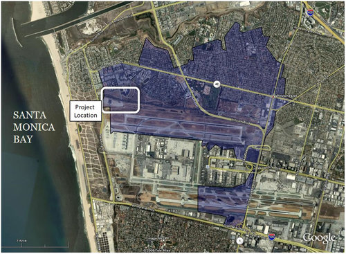
Source: City of Los Angeles, and AECOM
In fact, the project converts surface runoff discharge into groundwater recharge. The project is located on Los Angeles World Airport property, adjacent to LA’s Westchester neighborhood. It is designed to capture the first ¾ in. (1.9 cm) of rainfall that enters three major stormwater drains, known as the Argo Ditch, the City of LA Falmouth Drain and the County of LA drain #647—all of which discharge into Santa Monica Bay.
The first ¾ in. (1.9 cm) of rainfall is termed the “first flush,” which usually carries the highest concentration of pollutants.
The collected stormwater from these three sources is routed to a lift station that pumps it to a rectangular clarifier for removal of debris and particulates. This solids removal operation occurs in a below grade concrete structure 120 ft. x 20 ft. x 17 ft. (36 m x 6 m x 5 m) deep.
The flow then enters a reinforced concrete tank, 250 ft. (76 m) diameter x 27 ft. (8 m) deep, also completely below grade. This tank functions as storage for infiltration through the open tank bottom and through 18 dry wells, each 100 ft. (30 m) deep x 12 in. (30 cm) diameter. The tank and the dry wells can infiltrate at a rate of 3 in. (7.6 cm) /hour, with a total potential to create over 1 million gallons/day (3,785 m3/day) of groundwater.

Argo Drain Flow scheme, flow left to right.
Source: Argodrain.com
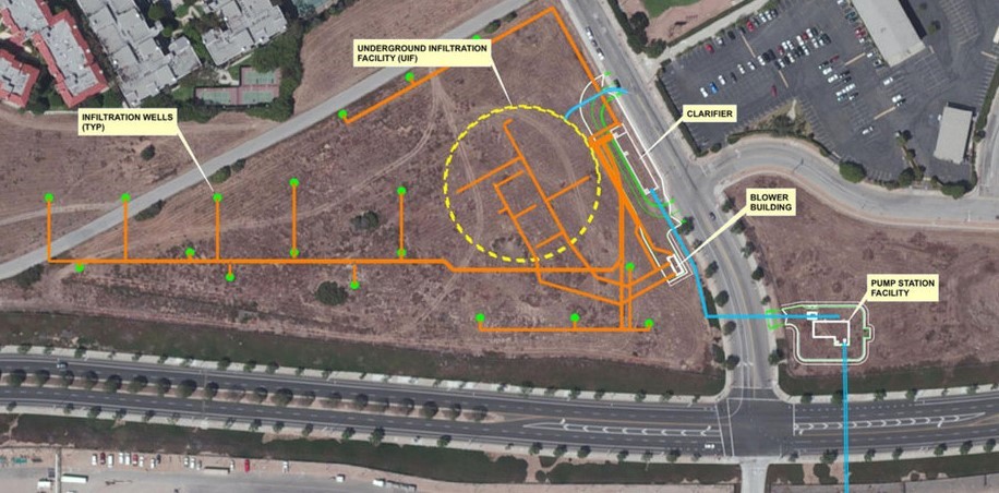 Argo Drain site plan showing underground structures, flow right to left.
Source: Engineering – City of Los Angeles and AECOM
Key to the successful operation of the project is the large 8.1 million-gallon (30,600 m3) storage tank. At a 27 ft. (8 m) structural depth, it was constructed of post-tensioned reinforced concrete. Consulting Engineers AECOM and Geosyntec Consultants designed the tank for both storage and infiltration, as the tank has an open bottom.
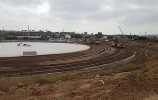
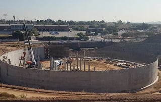
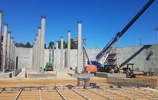
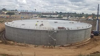
Argo Drain Storage/Infiltration Tank Construction.
Source: Project Management Construction Services
Except for the lift station, the entire project was designed to be located below grade, partially to provide greenspace and to ultimately create a new park within the city. The excavation for the tank was more than 27 ft. (8 m) deep over an area of over 1 acre (0.4 hectare).
To get maximum infiltration, vibration caused by compaction adjacent to the tank was undesirable. Geotechnical project consultants, Geosyntec, offered an alternative: the use of Expanded Polystyrene (EPS) geofoam adjacent to the tank in lieu of compacted fill. Geofoam has been gaining acceptance as an engineered product in many highway applications and, in this case, provided a lightweight solution to the need for backfill.
Geofoam is a hydrocarbon product and therefore can be attacked or solubilized by other hydrocarbons. The Argo Drain project site is, as are many areas in LA, subject to concern about in situ hydrocarbons and is located in a methane buffer zone. To alleviate the concern, a hydrocarbon- and methane-resistant geomembrane was specified to encapsulate the geofoam for long-term protection. The XR-5 geomembrane is the material of choice for DOT geofoam applications and when hydrocarbons and methane are a concern.
The XR-5 geomembrane liner was placed against the tank’s outside perimeter and was temporarily anchored at the top and bottom. Then, the geofoam was installed in large blocks that for stability were tapered in size with increasing elevation. Subsequently, the geomembrane was brought up the outside of the geofoam blocks and a perimeter XR-5 field weld was performed at the top of the geofoam block, thus encapsulating the entire geofoam.
Because the XR-5 is flexible, factory panels were made by EC Applications, Anaheim, California, for installation. Note that the factory seams are perpendicular to the hanging geomembrane. The XR-5 geomembrane has mechanical seam strength equal to the parent material strength, allowing more efficient construction with longer linear seams. Further, loss of seam strength because of heat absorbed from sunlight during construction is not a concern as it is with some geomembranes.
Fabricated panels were joined with minimal vertical field seams. The following photos illustrate the geofoam and XR-5 installation.
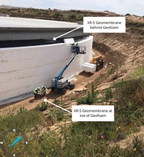
Geofoam/XR-5 Installation.
Source: EC Applications
-1.png?width=1152&name=XR-5%20Geomembrane%20on%20outside%20of%20Geofoam%20(2)-1.png) Geofoam/XR-5 Installation.
Geofoam/XR-5 Installation.
Source: EC Applications
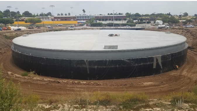
Completed XR-5 encapsulated geofoam.
Source: Project Management Construction Services
EC Applications completed the site installation of the XR-5 geomembrane in less than two weeks, utilizing approximately 35,000 sq. ft. (3,200 square meters) of material. Field welding was accomplished using automated hot wedge and hot air equipment under strict QA/QC protocols.
The Argo Drain project was completed in June 2021. The next phase will be to transform the site into a city park. Underneath it all will be a stormwater reclamation facility that has vital components protected for the long term by EC Applications and the XR-5 Geomembrane.
For more information, please visit www.xrgeomembranes.com and www.ecapplications.com
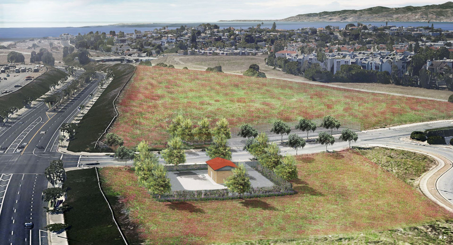 Rendering of finished project.
Source: Engineering – City of Los Angeles and AECOM

