This project profile details the design and installation of a geomembrane system to line an offshore containment bund for the government of Singapore.
Project Details:

Name: Pulau Semakau Off-Shore Landfill
Dates: Installed from 1995 to 1998
Location: Singapore
Project Story:
The Pulau Semakau project involved the construction of a 7-1/2 Km rock bund and cost $1.6 billion (U.S. dollars). Geomembrane represented the most reliable and easily constructed barrier for the perimeter bund. About one half of the 600,000 square meters of geomembrane were installed under water prior to dewatering of the containment area. The selection of the geomembrane and subsequent packaging, transportation, and installation are detailed within this paper. The unique constructability issues centered around the geomembrane properties including density, flexibility, and pre-fabrication, particularly compared to conventional clay containment systems. Data is also presented from other independent studies comparing the relative containment features of alternative lining systems.
INTRODUCTION
The tiny tropical nation of Singapore covers only 90 hectares (225 square miles) and is located at the southern end of the Malay Peninsula (see Figure 1). This flourishing nation of three million inhabitants is the world's busiest port and a major center of trade, banking, tourism, and communications. All of this prosperity means increasing concerns for waste disposal. In the early 1990's, Singapore began planning for replacement of the long used state owned landfill which was to be at capacity by 1998. The unique solution, proposed by the Ministry of Environment of Singapore, called for an offshore waste disposal facility to contain inert incinerated residue for the next 30 years. Relying on land reclamation techniques long employed in Northern Europe, the facility called for the building of a 7-1/2 km (4.2 mile) earth bund in water depths ranging from 10 m (33') to 20 m (66'), resulting in a 30 ha (75 acre) offshore waste pond. The bund served as a connecting wall between two offshore islands. Therefore, installation techniques were required for both dry and wet scenarios. In conjunction with various other hydraulic considerations, the seawater was to be displaced as the solid waste filling progressed.
CONTAINMENT DESIGN
The offshore bund was constructed by transporting and dumping 4.5 million metric tons (5 million tons) of rock and 36 million metric tons (40 million tons) of sand. The construction materials were transported from Indonesia. Figure 2 is the General Layout Plan for the Bund Project. The earthen wall connected several islands offshore from Singapore. Figure 3 illustrates the typical bund cross section which varied depending on the ocean depth. The offshore bund was created using stone with geofabrics for separation and filtration and sand was hydraulically installed in the body of the bund. A geomembrane was used on the interior surface of the dike, which was keyed into the seabed. Offshore investigations had shown that the seabed soils consisted of silt and clay of depths up to 10m (33')' overlaying rock with permeabilities less than 10-8 cm/sec. The project designers considered vertical leachate migration not to be a problem. The facility was designed to be operated with no net head difference from internal to external water levels. Therefore, hydraulic head forces on the containment layer are minimized. Rather, the interior of the bund was lined with a geomembrane which was then covered with a clay layer under the water level and rock at shore level. Outer slopes utilized geofabrics on a 1:3 slope (for shore protection) and inner slopes employed a flatter slope at 1:5. The construction of the bund is shown in Figure 4.

SELECTION OF GEOSYNTHETICS
Several lining materials were considered for the containment portion of the project including clay layers, Geosynthetic Clay Liners (GCL's), and various geomembranes. Selection criteria included Leakage Rate (theoretical) and constructability. Because of the difficult construction techniques involved, cost considerations were a minor selection criteria.
Leakage Rate (theoretical)
Hydraulic modeling by Tan, et al, showed that significant leakage rate potential reductions could be achieved using a geomembrane as opposed to a single clay layer or a clay layer and a GCL. Figure 5 illustrates the conclusions drawn as a result of this modeling effort.
This figure compares the lining alternatives on the basis of Leakage Rate Ratio, which is defined as:
Leakage Rate Ratio = Leakage No Liner / Leakage Liner (1)
Note also the following designations:
CL/GCL - Clay Liner/Geosynthetic Clay Liner
CL/GCL + CL - Clay Liner/Geosynthetic Clay Liner + Clay Liner
CL/GM - Clay Liner/Geomembrane Liner
CL/GM + CL - Clay Liner/Geomembrane Liner + Clay Liner
Leakage for the liner varies with the selected liner alternative. A GCL was shown to be 5-30 times better than the clay alone, a geomembrane liner 50-100 times better and a geomembrane with clay was 200-1000 times better. The ranges are dependent on head conditions.
Constructability
With the geomembrane/clay layer as the selected alternative, a material selection then concentrated on constructability. Field seaming and the use of large mechanical equipment for panel placement had to be minimized due to site constraints. There were two site installation scenarios, one was a "dry" installation in the areas of existing land, and the other involved a "wet installation", where the geomembrane would be installed from a barge into the ocean leading to the land.
Three types of geomembranes were considered:
- Reinforced Coated Fabric: Ethylene Interpolymer Alloy (EIA-RCF)
- Reinforced Laminates: Polypropylene and Chlorosulfonated Polyethylene (PPE/CSPE)
- Unreinforced Films (HDPE).
In the evaluation of constructability, the weights of the panels, along with associated friction angles for the considered materials are contained in Table 1.
| Material Type | Thickness | Panel Weight | Friction Angle GM/Asphalt | Friction, Tan S M/Asphalt |
|---|---|---|---|---|
| EIA-RCF | 1 mm | 30.2 KN | 22˚ | 0.404 |
| PPE/CSPE | 0.9 mm | 32.6 KN | 25˚ | 0.466 |
| HDPE | 2 mm | 45.5 KN | 18˚ | 0.325 |
Table 1. Geomembranes Evaluated for Constructability Issues
DRY DEPLOYMENT (Case 1)
In the first (dry) construction scenario, published friction angles were used to determine a theoretical safety factor when dragging the geomembrane into place.
Assume: Impact Load Factor (Dynamic) = 1.1
1-meter clamp bar @ tug points (worst case)
FTP = ForceTug Point = (Panel Weight x Tan S x Impact Load Factor)/No. Tug Points (2)
Fallowable = Yield Tensile Strength (3)
Calculate Factor of Safety (F.S.) in onshore dragging operation:
F.S. = Fallowable/FTP (4)
Table 2 summarizes the Force Tug Point, Allowable Force and Factor of Safety for each of the considered materials.
| Material Type | FTP | FAllowable | F.S. |
|---|---|---|---|
| EIA-RCF | 4473 N/M | 96,300 N/M (550lb/in) | 21.5 |
| PPE/CSPE | 5570 N/M | 35,000 N/M (200 lb/in) | 6.3 |
| HDPE | 5422 N/M | 16,800 N/M (100 lb/in) | 3.1 |
Table 2. Summary of Forces and Safety Factors for Dry Deployment Scenario
All geomembranes considered in this "dry"scenario analysis have safety factors greater than unity. However, the reinforced EIA Coated Fabric was 3 times as reliable as the laminated materials and 6 times as reliable as the HDPE film in this analysis. These conditions, of course, represent worst case conditions, but are representative of the possible forces to be encountered in this field operation. Folded panels ready for installation along the bund are shown in Figure 6.
OFF SHORE DEPLOYMENT (Case 2)
Figure 7 illustrates the forces anticipated in deploying and placing the geomembrane in the "wet" installation scheme:
Calculate Buoyant Weight of Geomembrane, w
W = Geomembrane Area (50m x 20m) x Bwu (5)
Where Bwu = Buoyant Geomembrane Unit Weight
FL = Force of Geomembrane in Water
FT = Force of Geomembrane on Barge
Note: Assume Ballast is assumed to be added to provide HDPES.G. = 1.2
Calculate force on Geomembrane as it is deployed from the barge:
FTP = (w x Impact Load Factor)/(Tan 45o x No. Tug Points) (6)
Calculate Factor of Safety (F.S.) in offshore dragging operations:
F.S. = Fallowable/FTP (7)
Note the materials with specific gravities (SG) less than 1 were assumed to require added ballast in order to provide a SG equal to the EIA-RCF, 1.25.
Table 3 summarizes the forces and theoretical safety factors for each material. While all exceed 1.0, the EIA-RCF geomembrane greatly exceeds the other materials.
| Material | Bwu | FTP | F.S. |
|---|---|---|---|
| EIA-RCF | 21.5 | 1,050 N | 91.7 |
| PPE/CSPE | 6.29 | 1,633 N | 21.4 |
| HDPE | 3.1 | 544 N | 30.9 |
Table 3. Summary of Forces and Safety Factors for Wet Deployment Scenario
Based on the constructability analysis, the following construction features were essential in the selection of the geomembrane:
- A portion of the geomembrane would be installed underwater and therefore a Specific Gravity >1 was needed.
- Ultimately, clay and rock would overlay the geomembrane which could result in some damage. A material was needed which would be most resistant to puncture.
- Large panels were needed which could be custom prepared based on both width and length. Field preparation of the material for fitting was to be minimized or eliminated.
- Overlapping rather than field seaming was to be used and then covered with the clay layer. Width was to be maximized in order to minimize amount of overlapping.
- Panel seams were to have maximum strength to withstand dragging and placement in the tropical environment, often under sustained loading. Abrasion strength was to be sufficient for installation.
The project designers created a specification that demanded the properties, listed in Table 4.
Ultimately, the supplied material was a reinforced Ethylene Interpolymer Alloy (EIA), manufactured as a Reinforced Coated Fabric.
| Material Type: | Reinforced EIA Geomembrane |
|---|---|
| Yield Tensile Strength: | 250 Kg (550 lbs) minimum |
| Dead Load Seam Strength (Mil-T-52983E Modified,Para 4.5.3.19, 25 mm strip, ASTM D751) | |
| 20 deg C | Pass @ 900N (210 lbs), 4 hour sustained load |
| 70 deg C | Pass @ 240N (105 lbs), 4 hour sustained load |
| Prefabrication Capability: | |
| Width | 30.5 m (100') minimum |
| Size | 1860 sm (20,000 sf) minimum |
| Specific Gravity | >1.2 |
| Thickness | 1 mm (0.040") minimum |
Table 4. Project Geomembrane Specifications
INSTALLATION
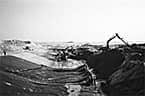
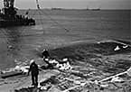
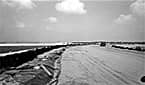
The selected material allowed the contractor to install the geomembrane and clay layer in sections as bund construction proceeded. The geomembrane was prefabricated into large panels of widths up to 18.2 m (60') and lengths as determined by ocean depth and subsequent bund design. Fabricated panels were accordion-folded for shipment to Singapore. This folding technique made installation of the Geomembrane very efficient with an unfolding sequence that minimized material handling. All sheet manufacturing and fabrication activities were subject to QA/QC procedures and field activities were conducted according to a CQA plan, all approved and monitored by the Singapore Ministry of the Environment.
Figures 8, 9 and 10 illustrate the Geomembrane unfolding and installation. Underwater divers were used to key the leading edge of the geomembrane to the ocean floor, shown in Figure 9. Figure 10 illustrates a completed bund area with the geomembrane in place. Sand and riprap were dumped over the geomembrane once it was installed. Installation of a typical panel required 1 day.
CONCLUSIONS
This project illustrates the versatile constructability of geomembranes as opposed to traditional clay-type materials. Without the use of a geomembrane, it is estimated that construction of the entire disposal facility would have been impractical, requiring different design techniques and different environmental constraints.
The Pulau Semakau accepted its first shipment of waste in March 1999.

ACKNOWLEDGEMENTS
The geomembrane used in the bund construction was XR-5®, manufactured by Seaman Corporation, Wooster, Ohio, USA. The Panel fabricator was Lange Containment Systems, Denver, Colorado, USA. Project designers were Camp, Dresser and McKee Intl and Specs Consultants Pte. Ltd., both of Singapore.
REFERENCES
Tan, S.A., et al, "Leakage Study Across an Offshore Waste Containment Bund", Proceedings, 1998 Sixth International Conference on Geosynthetics, Atlanta, Georgia, 1998.
By Felon R. Wilson, P.E., Seaman Corporation
United States of America
Reprinted from "Proceedings, Geosynthetics 2001", Portland, Oregon, USA, February 2001.